Build your own
(2026 notice) This page describes an old project, and it may be incomplete.
The design of my multi-toe tracker is made public, but the components I provide as a reference are built to fit my foot shape.
In order to adapt the work to your own foot, you will need to adapt or redesign components yourself, and therefore will need to have existing familiarity with CAD software. Also, you will probably need your own 3D printer as it is unlikely that you will design the correct part on the first try.
Materials used
Quantities for 2 feet. Divide by 2 if you only want to make one foot.
| Quantity | Item I have used | Where I got it from |
|---|---|---|
| 6 | Flex sensor (2.2 inch = 5.6 cm) | https://www.aliexpress.com/item/33006987477.html |
| - | Printing filament: Flexible TPU 95A shore | https://www.amazon.fr/dp/B07R7SCM5G |
| 6 | Mini Micro JST 2.0 PH Male Female Connector (2 pins = 2P) | https://www.aliexpress.com/item/4000091077742.html |
| 6 or 12 | Several 10K ohm resistor | |
| - | Electrical tape |
Option 1: Tundra Tracker with Developer board
Quantities for 2 feet. Divide by 2 if you only want to make one foot.
| Quantity | Item I have used | Where I got it from |
|---|---|---|
| 2 | Tundra Tracker | https://tundra-labs.com/ |
| 2 | Tundra Tracker Developer Board | https://tundra-labs.com/products/tundra-tracker-developer-board?_pos=1&_sid=eb963e1e3&_ss=r |
| (2 or 1) | - 14 Pin JST IO Cables | Already included in the items provided alongside the Tundra Tracker Developer Board. You can cut in the middle to produce 2 separate male connectors. |
My implementation requires the use of 3 ADC pins on the Tundra Tracker develoepr board.
Option 2: ESP32 or similar
I will not provide a list of materials for this option, as I don't have the full materials list for all the components necessary to build a self-contained battery. Building a self-contained battery should be similar to SlimeVR.
My implementation requires the use of 3 ADC pins, while the WiFi is connected.
Assembly notes
Most of the item-specific assembly notes are specified in the CAD section.
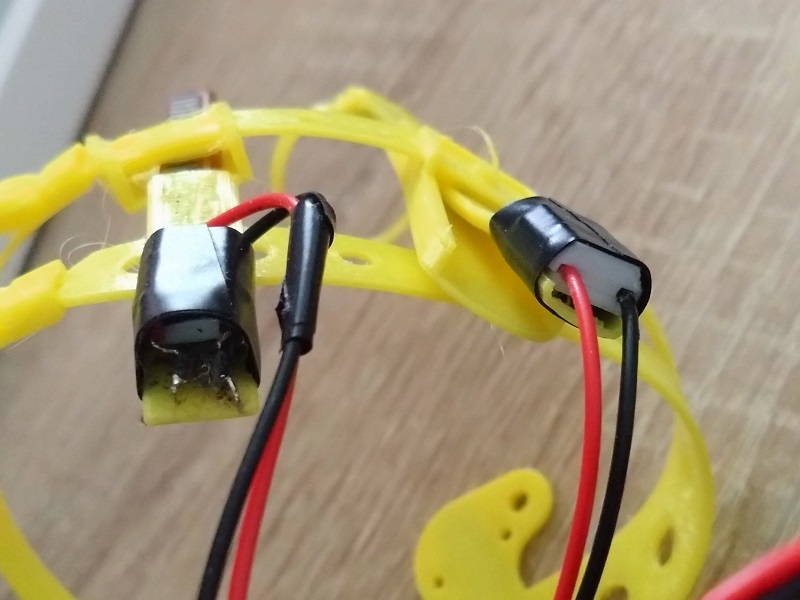
The solder joints on the flex sensor must be relieved of stress by finding a way to clamp the wires, so that the wires itself bears mechanical stress.
I've personally 3D-printed a small wire clamp which is secured using a screw and a heat-set insert, but there must be easier ways to do this using some thin metallic clamps.
